Mechanical drawing symbols are used to represent physical objects in a technical drawing. They are used to help engineers and architects communicate with each other about the design of various objects. There are dozens of different symbols that can be used, but most share a few common elements.
For example, a line is used to represent an edge or plane, and rectangles are commonly used to illustrate objects with flat faces. Circles can be used for tubes or holes. Arrows are often employed to show the direction of motion or rotation.
These symbols provide a quick visual way for professionals in the engineering field to communicate ideas and explain designs more effectively than words alone could do.
Additionally, mechanical drawing symbols can provide information about size and scale, material type, and even surface texture. This makes them invaluable tools when it comes to designing complex machinery or structures that require exact specifications. By using proper symbols on technical drawings, engineers can ensure that their designs are built correctly and efficiently.
In conclusion, mechanical drawing symbols provide an efficient means of communication between engineers and architects. They facilitate the quick exchange of ideas while providing specific information about size, shape, material type, and other important details. With the help of these symbols, any design project is sure to be successful.
What Are the 5 Types of Mechanical Drawings?
1. Detail drawings: These are used to provide precise details on how a part should be manufactured or assembled.
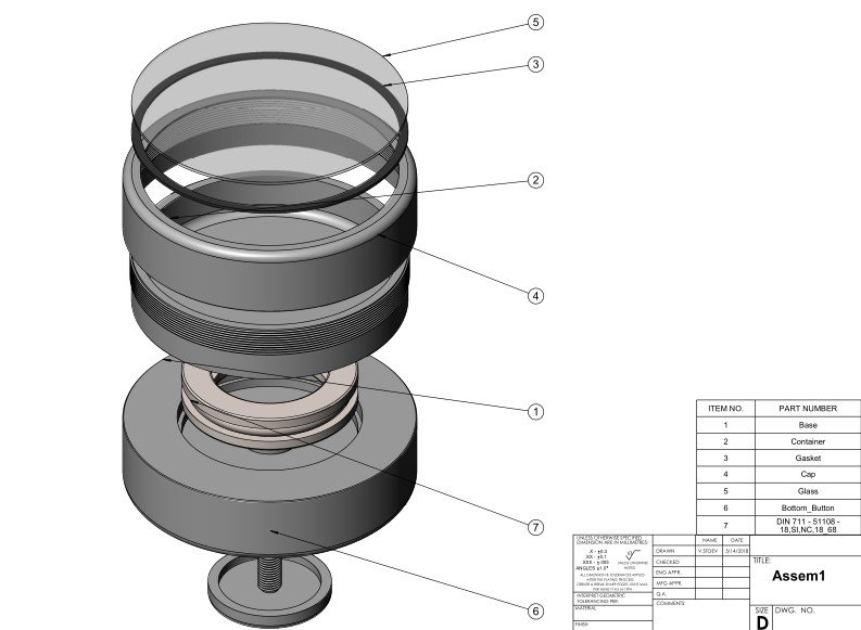
2. Assembly Drawings: These diagrams provide an overview of the various components that need to be put together to build a machine or device in its entirety.
3. Isometric Drawings: This type of drawing provides a 3-dimensional view of the object, allowing for more detailed measurements than traditional orthographic views.
4. Orthographic Drawings: Orthographic drawings use two or more views (top, front, side) that are projected onto the same plane.
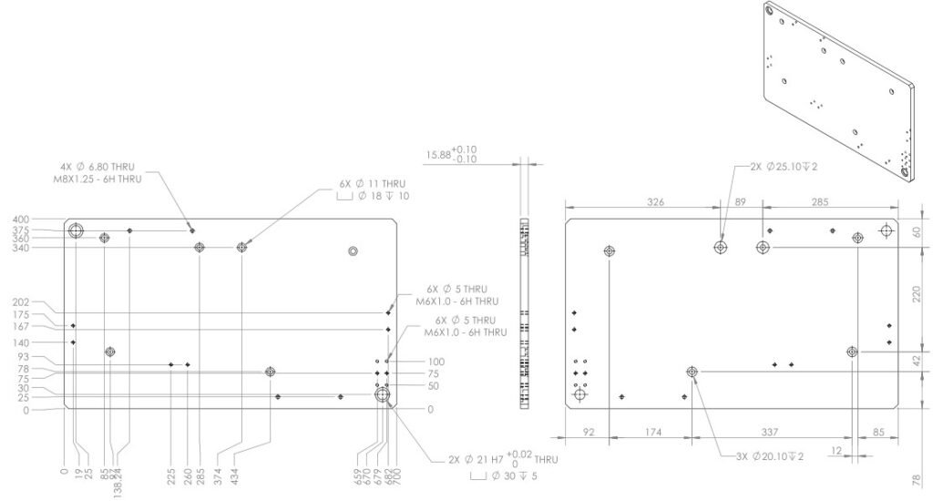
5. Dimensioned Drawings: These drawings provide measurements and tolerances to ensure that the parts are machined or assembled correctly. They can be used to check parts against a set of specifications or standards.
What are Mechanical Drawing Symbols
Mechanical drawing symbols are used to represent different components in a mechanical system. These symbols can include lines, circles, squares, rectangles, and other shapes. The size and orientation of each shape may have specific meanings in the context of the overall diagram. For example, a large circle might represent a motor while a small rectangle could signify an electrical switch. Additionally, arrows or dashed lines may be used to indicate motion or flow between components. Different colors can also be used to differentiate parts from one another based on their function or purpose. Symbols are typically standardized across various engineering disciplines so that anyone familiar with them can interpret them correctly regardless of the type of project they are working on.
Common Engineering Drawing Abbreviations
are also used to provide concise information on components and processes. These abbreviations can include acronyms such as “CAD” for computer-aided design or symbols such as “N/A” for not applicable. Knowing these abbreviations is essential in being able to interpret mechanical drawings correctly.
Cross-referencing other documents, such as parts lists or assembly manuals, is also important when interpreting mechanical drawings since it allows the user to confirm that all of the parts shown in the diagrams are present. This can help to ensure that all components are included and accounted for before beginning any type of construction project. With appropriate knowledge and practice, anyone can become an expert at understanding mechanical drawing symbols and abbreviations.
AF: Across Flats
ASSY: Assembly
ALUM = Aluminum
ALY= Alloy
AMT= Amount
AB = Anchor bolt
APPROX= Approximate
C TO C = Center-to-Center
CAM = Computer-Aided Mfg
CB= Counterbore
CARB = Carburize
CM: Centimeters
CL: Centerline
CU: Copper
TOL: Tolerance
V/C: Volume Control
W/O: Without
WT: Weight
XFMR: Transformer
IN: Inch
FT: Foot
D: Diameter
DC: Direct Current
AC: Alternating Current
XREF: Cross Reference
N/A: Not Applicable
CAD: Computer-Aided Design
MATL: Material
MAX: Maximum
MIN: Minimum
SLV: Slave
LB: Pound
RAD or R: Radius
I/D: Internal diameter
O/D: Outer diameter
FRAC: Fraction
SIG: Signature
APPR: Approved
HRC: Hardness Rockwell C scale
HRA: Hardness Rockwell A scale
L.B.: Left Bottom
R.T.: Right Top
FAB: Fabrication
BLK: Block
VOL: Volume
WT: Weight
LEN: Length
WID: Width
DIA: Diameter.
ANN: Anneal
CNC: Computer Numerical Control
CTR: Center
DIN: Deutsches Institut Fur Normung (German Institute for Standardization)
FNC: Function Code
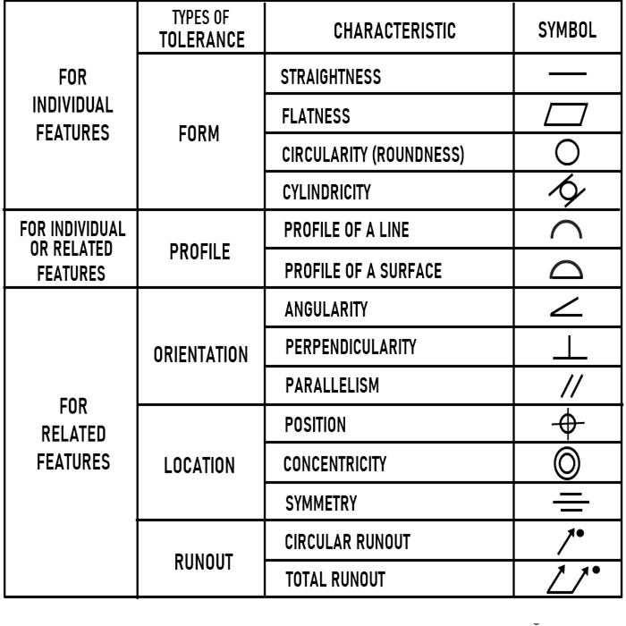
G&T: Geometric and Tolerancing
HIP: Hot Isostatic Pressing
ISO: International Organization for Standardization
KAR: Kinematic Analysis and Reversal
MMC: Maximum Material Condition
MSG: Multiple Start Groove
RTP: Roughness Texture Parameters
STC: Starting Current
TIR: Total Indicated Runout
TTL: Through The Length.
W/P or P/W: Welded or Plug
MFG: Manufacturing
DIM: Dimension
ED: Edge distance
IAW: In accordance with
THD: Thread
TPI: Thread per inch
VOL: Volume
WT: Weight
CSK: Countersink
CHAM: Chamfered
CYL: Cylinder
EQUI SP: Equally Spaced
HEX: Hexagon
LH: Left hand
NTS: Not to scale
GDT: Geometric Dimensioning and Tolerancing. This is a system for specifying specific measurements and the acceptable tolerances in which parts may vary from their desired specifications. GDT is used to ensure that manufactured parts are interchangeable, regardless of who produces them. It can also help to reduce production costs by making sure that the same component can be produced multiple times with minimal variation.
These abbreviations will be used on mechanical drawings in order to provide concise information about components and processes. By familiarizing oneself with these symbols and abbreviations, one can better understand the diagrams associated with any mechanical system. Understanding mechanical drawings is an essential part of engineering and manufacturing that allows for the efficient creation of complex machines and devices. With a good understanding of drawing symbols, abbreviations, and cross-referencing other documents, anyone can become proficient at interpreting mechanical drawings.
Different Types of Mechanical Drawing Symbols
Mechanical drawing symbols are used to represent components and processes in diagrams. These symbols can include lines, boxes, circles, arcs and text. Lines are typically used for connecting different objects or parts of a diagram together, while boxes are used to show the size and shape of objects. Circles and arcs can be used to denote curves or round features on an object. Text is also commonly included with mechanical drawings as it provides abbreviations that describe certain measurements or properties. Additionally, some symbols may have arrows indicating directions or directions of movement such as those seen in flowcharts and piping diagrams.
These symbols are standardized across different industries, so that manufacturers and engineers around the world adhere to the same guidelines when creating drawings. By understanding those symbols in drawing, this helps to ensure that any part specified in one drawing is the same as any other part described with the same symbol in another diagram. By understanding the various types of mechanical drawing symbols, anyone can become proficient at reading diagrams and interpreting engineering plans.
Conclusion
By utilizing abbreviations and symbols in mechanical drawings, engineers are able to quickly convey information with fewer words. This helps to reduce the amount of time spent deciphering diagrams and reduces errors that can occur from misinterpreted instructions.
Overall, incorporating abbreviations and symbols into mechanical drawings is essential for efficient engineering and manufacturing processes as it reduces errors due to miscommunication between designers, manufacturers, and engineers. By familiarizing oneself with these symbols, one can easily read diagrams and interpret engineering plans.
Having a good knowledge of mechanical drawing symbols also helps to ensure that components are interchangeable between different manufacturers and applications, reducing production costs and increasing efficiency. Familiarity with these symbols is the key to becoming proficient at interpreting mechanical drawings.
