Even though CAD files can be used directly for programming the CNC machines, there is still much information that can’t be conveyed from 3D files, like thread, tolerance, and surface finishing. Maybe you don’t need these features, but on most occasions, it’s still necessary to provide technical drawings to manufacturers for quality control purposes.
What are Technical Drawings and Why They’re Important
Technical drawings are documents that convey detailed information about CNC machined parts. They provide all the critical details necessary to manufacture CNC machined parts and ensure they meet the required specifications. This includes dimensions, tolerances, and surface finish requirements as well as other special requirements such as specific materials or surfaces that must be used.
Technical drawings are essential for accurate CNC machining and precision parts. Firstly, technical drawings provide CNC machinists with the detailed information they need to accurately produce CNC machined parts. Secondly, technical drawings also help CNC machinists identify any potential problems before CNC machining begins.
The two main types of technical drawings used in CNC machining are geometric dimensioning and tolerancing (GD&T) and computer-aided design (CAD).
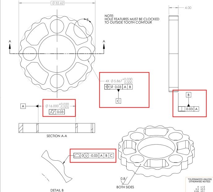
GD&T is a system of symbols and conventions used to convey detailed information about CNC machined parts. CAD is a system of symbols and programming language used to create 3D models of CNC machining parts that can be manipulated in the computer for accurate machining.
What Should be Included in Technical Drawings?
Technical drawings for CNC machining should include all necessary dimensions and tolerances, material specifications, surface finish requirements, any special requirements such as hardening or heat treatment, and a clear view of CNC machined parts from all angles. It is also important to include any CNC machining notes such as special instructions or updates that may affect CNC machining accuracy.
Besides, a technical drawing should also include hole callouts as well as thread specifications, they are necessary to make correct parts. Below are more features and views to include on an engineering drawing:
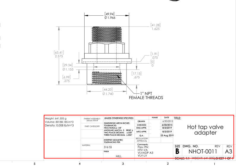
Title block: it should contain information about the company name, document title, drawings number, material requirements, surface finishing requirements, standards used, etc. It’s often put in the bottom right corner of the whole drawing.
Notes to manufacturers: notes are used to provide more detailed instructions about the CNC machined parts, for example, you may include notes on specific handling or assembly requirements.
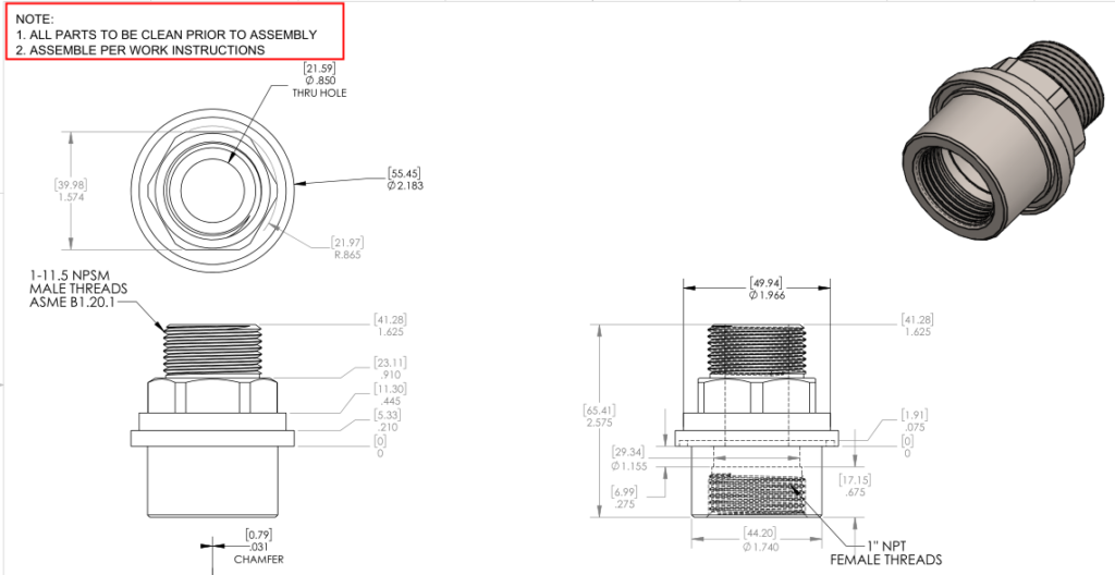
Orthographic View: This view shows the profile of CNC machined parts from many different angles and is determined by the overall shape of the component.

Section View: section view shows the internal structure of CNC machined parts, it’s an important feature as many components have complex internal structures that need to be machined accurately.

Isometric view: 3D representation of CNC machined parts, including all angles and surfaces.

Detailed view: It mainly highlights some critical view that requires high CNC machining accuracy. It should clearly show any critical CNC machined parts dimensions and tolerances as well as any special requirements.

How to Create a CNC Machined Part from a Technical Drawing
In order to make technical drawings for CNC machining, you need specialized software. This can include CAD software such as AutoCAD and SolidWorks or GD&T tools like Geometric Dimensioning and Tolerancing.
Once the technical drawing has been created, it can be used to create a CNC machined part. This involves preparing the necessary materials and tools, setting up the machine, and programming the CNC machine with the correct instructions. Once the program is running, CNC machinists can monitor and adjust as needed to produce precision parts according to the technical drawing.
When making a CNC machined part, it is important to closely follow the technical drawing and adhere to all specified tolerances and dimensions. This ensures that the finished product matches the specifications of the technical drawing, giving customers exactly what they asked for.
Additionally, following all instructions in the technical drawings helps prevent mistakes that could potentially damage the CNC machine or result in incorrect parts.
Benefits of Technical Drawings for CNC Machining
Using technical drawings for CNC machining comes with a number of benefits. Firstly, it provides detailed and accurate instructions for producing precision CNC machined parts, making them easier and faster to create.
Technical drawings also allow CNC machinists to create parts with repeatable accuracy, making it easier to produce multiple identical parts quickly and cost-effectively. This is especially important in industries where precision and repeatability are essential, such as medical or aerospace engineering.
Moreover, technical drawings can help CNC machinists and QC staff members to conduct quality control. The drawings provide exact measurements and tolerances that can be used to check if the parts match the intended specifications. This makes it easier to spot any potential mistakes or issues before they become a problem.
Overall, technical drawings provide CNC machinists with a powerful tool for creating cnc machined parts that meet all specifications and requirements. With the right skills and software, CNC machinists can use technical drawings to quickly create precision CNC machined parts with repeatable accuracy.
7 Steps to Prepare a Technical Drawing
Below are some simple steps to draft technical drawings for CNC machining.
Step 1: Define the views required. The first step in creating a technical drawing is to decide what views are required and put the orthographic in the drawing center.
Step 2: Try to add a section view or detailed view if your parts have some internal features.
Step 3: Add construction lines for all views. Start with the most complex view first and then draw out the other views.
Step 4: Add dimensions for your CNC drawings.
Step 5: Create threads, and specify their size, length and location.
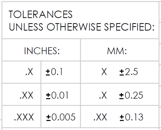
Step 6: Apply standard tolerances and also higher tolerances for those features which needed.
Step 7: Fill in title blocks and other relevant information like surface finishing.
The above is just a basic structure to make technical drawings, make sure to add all dimensions, tolerances, and surface finishing.
Tips for Adding Dimension, Tolerances, and Annotations
When creating technical drawings for CNC machining, it is important to add the correct dimensions, tolerances, and annotations. Here are some tips to help make sure that all relevant information is included in your CNC drawing:
– Specify units of measure (metric or inches)
– Include all necessary dimensions for CNC machined parts
– Use standard tolerances and specify any special requirements
– Include surface finish details (coating type, roughness values)
– Provide all necessary notes and annotations
– Check for accuracy by running CNC simulation programs if available
Creating technical drawings for CNC machining can seem overwhelming, but following the steps and tips above can help ensure that your CNC drawing is accurate and complete. When done correctly, CNC drawings provide detailed instructions for CNC machinists to create precision parts quickly and cost-effectively.
Conclusion
To conclude, now you may have a better understanding of the importance of technical drawings and how to create them, and technical drawings are essential for CNC machining, providing an accurate framework for creating precision parts quickly and cost-effectively. When used correctly, technical drawings can help reduce errors and mistakes while ensuring repeatable accuracy.
Thus, they provide an invaluable resource for CNC machinists who are looking to create high-quality parts according to given specifications.
In order to make sure that the technical drawings are accurate and complete, one should pay attention to details such as units of measure, dimensions, tolerances, surface finish, notes, and annotations. Following these steps and tips can ensure that your technical drawing for CNC machining is correct and helps you create precision CNC machined parts quickly.
